The Flip-Flop Component converts a trigger type input to a Boolean type output.
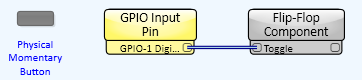
Use Case 1 - If you want a physical momentary button to act like a toggle button.
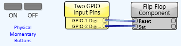
Use Case 2 - If you want two physical momentary buttons, one to turn something on, the other to turn it off.
When a trigger type control is wired to any one of the Flip-flop's trigger inputs, every time the trigger type control is triggered, the Flip-flop responds. When a Boolean control is wired to a Flip-flop trigger input, the Flip-flop responds when the Boolean control changes to true.
|
Control |
Function |
Default/Range |
|---|---|---|
|
Set |
A trigger that sets the State to True |
N/A |
|
Reset |
A trigger that sets the State to False |
N/A |
|
Toggle |
A trigger that toggles State |
N/A |
|
State |
Represents the state of the flip-flop. This control can be stored in a snapshot. The value of the State button is restored on startup. Although it is a toggle button, it isn't normally use it as such. |
True/False |
|
Out |
Read-only LED. The value of State. |
N/A |
|
Not Out |
Read-only LED. The complementary value of State. |
N/A |
There are no Properties for the Flip-Flop Component except for the Color.
|
Pin Name |
Value |
String |
Position |
Pins Available |
|---|---|---|---|---|
|
Not out |
1 0 |
true false |
1.00 0 |
Output |
|
Out |
1 0 |
true false |
1.00 0 |
Output |
|
Reset |
Trigger |
Input / Output |
||
|
Set |
Trigger |
Input / Output |
||
|
State |
1 0 |
true false |
1.00 0 |
Input / Output |
|
Toggle |
Trigger |
Input / Output |
||
© 2009 - 2016 QSC, LLC. All rights reserved. QSC and the QSC logo are trademarks of QSC, LLC in the U.S. Patent and Trademark office and other countries. All other trademarks are the property of their respective owners.
http://patents.qsc.com.
![]()
 Related Topics